In the first episode of the budget home networking series we had a look at how to cable our home, which components to put in such as a 19 inch rack, a patch panel and a switch and what type of cables and racks to use. Today we will look at how we can interconnect and extend these devices in order to have a good Internet connection in the whole house.
One of the central components of the cabling infrastructure is the patch panel. This is where all the cables from the house come together. For example this outlet goes to the living room, meaning there is a connector in the living room and a cable going from there to this point here. Some of you were asking if you really need a patch panel and there are also you tubers saying that you don‘t need it for small homes.
In fact, the size of your home is not the most important factor but rather the number of devices that you want to wire. Of course - generally speaking - those two parameters go somehow hand in hand. In other words, if you only want to connect 2 or 4 devices then a patch panel would probably be slight overkill – you can have one but you don‘t have to.
You could as well just crimp a connector to the cable coming out of the wall and plug it into the switch directly. Let’s quickly go down to the lab in my basement and have a look at how these cables can be crimped If you want to skip this, use the chapter or time markers.
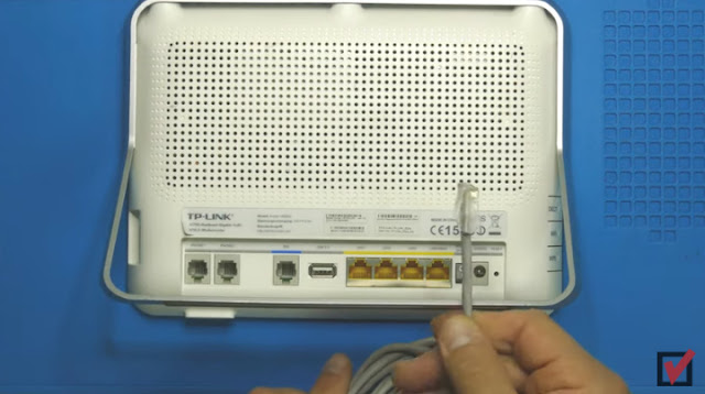
Okay guys. This is what we have. This is the cable coming out of the wall - in my case it’s a cat 5 cable and we want to connect to our ISP’s router. I am showing the back side here. And in fact we have that switch portion here. The LAN switch portion here and we want to connect that cable to this LAN switch portion. Of course - what we do need in order to do that is, we need a an rj45 connector - a normal Ethernet connector like this one. I am using unshielded cat5 cable for this.
Depending on what type of cable you have you might need to use a different type of connector here and then we can just simply click it into that connector here and we don’t need a patch panel for that. So how do we do that?

We need a special tool for this. The tool which I am using here is really a very cheap tool. I bought this many years ago. When I was still a student I think ;-) and every euro, every dollar every cent mattered. It was very cheap like I don’t know three or five euros at the time. What this does... If we look at that connector which we will be using… This connector has… they come in various different types. There are connectors which have a distance holder here that you put in where the cable goes in so it makes sure that the wires are at the right distance. These ones are cheap variations. They don’t have that. You just need to push the cable in and then there is those little metal contacts here that will actually make the contact with the wall connector - with the connector of our router or switch rather.
And if we look at it - this one has not yet been crimped and (I hope you can see that on the camera) the metal blades actually stand out of the plastic here. Once its crimped that metal will be pushed into the plastic connector and there is actually like I would say little knifes or blades here inside. They will actually be pushed onto the wires and this is where the electric contact happens. So using that tool, we will put the cable with the connector into the tool. There is two things that will push here. The first is that comb style piece here that will push the little blades or connectors into the little slots here and the other one actually pushes that plastic part here further down and that will actually hold the cable back from getting disconnected when you pull on it.
I opened those and made them loose, opened those screws. Then the whole thing was moving and then I pushed it into the connector and then I screwed it back on. Again - if you do have a tool of a better quality - a more expensive tool - that will save you a lot of hassle. But if you’re only doing this once then a cheap tool might do. But if you can let’s say borrow a more expensive tool of higher quality that’s definitely worth it. For this video I will use my cheap tool just to show that it is feasible, that it can be done.
First thing we do - we cut that part of the cable that comes out of the isolation so we have a proper ending here. And the nice thing with these tools is that they have two cutters here and that distance holder that will actually cut the cable at the right distance. Don’t cut too deep, just a little bit without applying force. Then you can rip off the isolation. Once more in detail. Let me cut this one off. Once more. Let’s get rid of the isolation here. Here’s the two little cutters. I put the cable in and apply very few pressure then turn it around a little bit so that it cuts the isolation all around and once I pull it back it should actually rip off the isolation at the right distance.

What’s that - about an inch or something like that ? And if you look at the connector the cable needs to actually go until the end of the connector where those little nicer little metal contacts are now the next thing we need to do is we need to put the cables into the right order and you remember there’s two different norms and what you basically need to do you need to put them into the same order like you do on the other side of the cable so the connector part here needs to have the same color coding like the connector on the on the other side of the cable has in my case that’s variation b meaning white orange white green then comes blue and white blue then comes green it takes a bit of experience and patience to actually do that what I do from time to time I just hold them together and move them like this that flattens the cable because it needs to be flat to go into the connector don’t worry too much about the distance here for the time being we will cut the cable exceed in a second and then white brown and brown right.
So they should be roughly in the right order here you can also hold them and pull the isolation back a little bit that helps because once we push it in we will push it back good so here we go I think we should have the cables in the right order yes we do that’s perfect and next thing we do we just cut the cable exceed a little bit just so that they are all at the same height or distance right so just cut them off now you can see them nicely forming a nice line and then we can take that connector and push them into that connector and don’t worry the cables the little wires will find their way through the little slots that are inside you need to push them really hard because what we want to achieve i hope you can see that on the camera we want the end of the wires to appear here at the plastic at the plastic end of the connectors I already pushed them in hard so here we go so you can probably better see it from this side.
So they are really pushed in nicely and then what we do we just put it into the tool from this side clip it in and now the tool this comb shaped part of the tool will actually push the metal contacts onto the wires and create a contact with these cheap tools do not hesitate to do it a couple of times here we goand here’s our connector and as you can see it also pushed the plastic part onto the isolation and that really holds it back from being ripped out when you pull out the cable right not too difficult totally feasible I admit it takes a bit of patience it takes a bit of experience it takes a bit of time but in other words if you if you buy those connectors do not and you need to crimp two don’t buy just two by ten right you might actually waste a couple of those but it’s totally feasible.
So once we’ve done that we can then check the connection with such a cable tester here what you would do on one side of the connection so where your wall outlet is with a little patch cable you would connect that part of the tester to the wall outlet let me just actually do simulate that by putting the other end of the cable to the tester and then the other end of the cable which we’ve just crimped we put it into that part of the tester and then it will check all the pairs one pair after the other one and two three and six four and five seven and eight and indicate with a green led that the connection is made in the right way that’s it. The second central component here is the switch. This is the part of our installation that interconnects all the Ethernet components, that means our PCs, Laptops, Printers, Raspberry Pis and so on if you want to wire them rather than use Wi-Fi. The good thing with switches is that they can be interconnected.

So in other words you can not only connect a PC or printer or any other Ethernet device to a switch, but you can also connect another switch. Let‘s actually do this as a first step and connect the switch portion of our ISPs router to the central switch.Mini Lab – connecting the switch portions all I do really is use one of these patch cables or Ethernet cables and plug it into the switch portion of my ISPs router. That’s the yellow connectors here. Let me plug this in and then put the router back to the wall. The other end goes into the switch in the rack and I can now connect not only four but rather 16 or 24 devices to the network.
While I am at this let me also connect the outlet going to the kitchen, to the living room and to the bathroom to the switch and hence provide Ethernet network connection to the outlets located in those rooms. As you can see, those patch cables come in different colors and lengths – it’s a question of taste rather than technical functionality if you want them shorter or longer or if you want to make them on your own or if you want to buy them ready-made. So which devices would you typically want to connect to your cabled or wired environment rather than using them over Wi-Fi ? After all, the commercials for Wi-Fi equipment promise excellent coverage in the whole house and full 4K streaming bandwidth for everybody these days.
Like so often – I’d say – remain realistic. The commercials is one thing, the reality is another. As a rule of thumb, I would say strive to use hard wire rather than Wi-Fi for as many components as possible. Especially those which use a large bandwidth. Typical candidates for this are PCs and Laptops which constantly live at one given place such as your desk. Another good candidate for cable or wire is the TV or everything that streams Multimedia content. I mean, look at it – every device that we remove from the Wi-Fi frees up bandwidth for the real mobile devices such as tablets or phones which do not have cable connectors like Ethernet. So we don’t really have a choice there. You may find many other devices which you can actually connect to Ethernet even if you maybe didn’t realize it until now – such as your printer for example.
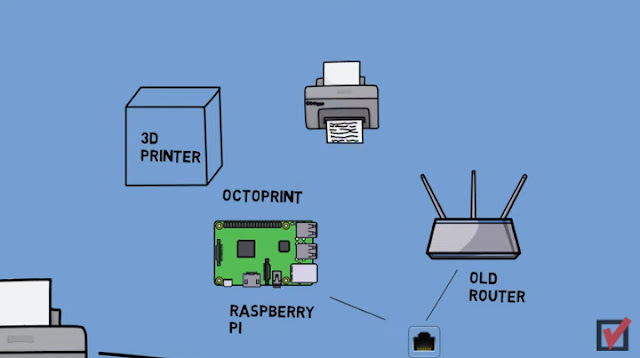
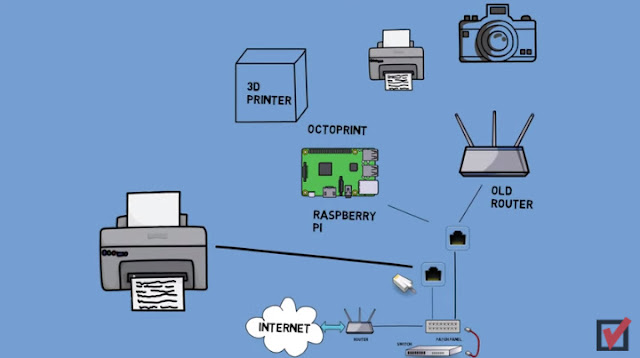
You might want to check if it has an Ethernet port. If you take things even further, then you might even find that you could actually make additional devices network-capable using an additional gateway such as a Raspberry Pi or an old router running OpenWrt as long as it has a USB interface. You could for example turn your 3D Printer into a network printer by adding a Raspberry Pi which runs Octoprint to it. Or you could connect that old inkjet printer to a USB port of a router and hence make it network-capable. Or add a USB camera to the network by attaching it to a router – watch my videos on those subjects – I’ve put cards up here – just click on the little info icon to watch them.
For additional components such as a NAS box (that is short for Network Attached Storage and basically is a file server) or a second access point we would do exactly the same like for the other devices, that means just connect them directly to the switch. We either place them in the 19“ rack or we connect them over the patch field if they are located in another room. Cool, so now we have our ISPs router connected to the ISP, our Switches interconnected and the outlets in the various rooms are connected with patch cables.


Comments
Post a Comment